


What Is a Sheave?
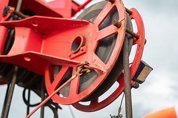
 A sheave is a grooved wheel designed to guide, support, and redirect a rope, cable, wire rope, or belt under load. Sheaves are commonly used in lifting, tensioning, and power-transmission systems to manage motion, control direction, and distribute forces within mechanical assemblies.
Sheaves Versus Pullies
In many industrial contexts, the terms sheave and pulley are used interchangeably, but they do not technically refer to the same thing.
- A sheave describes the grooved wheel itself, the component that directly supports and guides a rope, cable, or belt.
- A pulley, by contrast, refers to the broader assembly that incorporates one or more sheaves along with a frame, shaft, bearings, and mounting hardware.
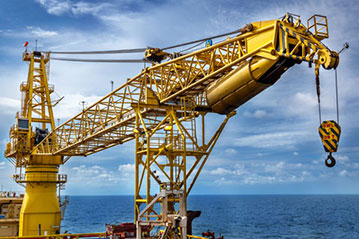
In some systems, like cranes, multiple sheaves may be employed together as part of the overall pulley system.
In practice, the distinction between the sheave itself and the entire pulley matters most in component engineering and maintenance discussions, where separating the sheave from the surrounding hardware helps clarify design choices, material selection, and failure points. We take a deeper look at the distinction between a sheave and a pulley in our article here.
Sheave History
Sheaves are among the oldest mechanical components in human engineering, with early versions appearing in primitive cranes, hoisting systems, and construction tools as early as Ancient Egypt, thousands of years ago. These early systems relied on simple wooden or stone cylinders paired with natural fiber ropes, enabling humans to lift heavier loads and redirect force with far greater efficiency than raw strength alone.

These early designs reflected many of the same design principles that go into engineering pulleys today. According to this EXARC piece: “the (circumferential) portion of the cylinder in contact with the rope would be grooved to maintain the rope’s cross sectional integrity and roughened sufficiently to prevent rope slippage and related abrasion. Except for this grooved area on the cylinder, readily available lubricants, for example, olive oil or rendered animal fat, would be utilised on the cylinder and cradle mating surfaces.”
As engineering advanced, so did the demands placed on sheaves, which became integral parts of the pulley systems used everywhere from sailing blocks to cranes. The widespread adoption of steel wire rope, powered lifting equipment, and industrial machinery in the nineteenth and twentieth centuries dramatically increased potential loads, speeds, and operating cycles.
Modern sheave design reflects another step in this evolution. Advances in polymer science, composite materials, and bearing technology have expanded the design space well beyond traditional metals. As we explore below, today’s sheaves may be engineered to reduce corrosion, operate without lubrication, minimize noise, withstand extreme environments, and support highly specialized applications.
Anatomy of a Sheave
 A sheave is best understood as a modular assembly, made up of several distinct components that work together in lifting, tensioning, and motion-control systems. While configurations vary by application, a typical sheave system may include:
- Sheave: The grooved wheel that supports and guides the rope, cable, wire rope, or belt
- Bearing: The internal component that allows the sheave to rotate around a shaft or pin
- Thrust washers: Elements that manage axial loads and protect adjacent components from wear
- Shaft or pin: The fixed axis around which the sheave rotates
- Side plates or frame: Structural elements that capture and support the sheave and shaft
- Block or housing: The larger assembly that integrates one or more sheaves into a complete pulley system
Together, these components form a flexible, application-specific system that can be configured for a wide range of loads, environments, and operating conditions.
Sheave Design Standards
The following standards are helpful as a starting point for sheave design. As we explore in the following sections, however, these sheave design standards need to be carefully evaluated in context when engineering a system for a specific use case.
When designing custom or standard sheaves (prototypically comprised of nylon) the basic design of any sheave should conform to the appropriate minimum pitch diameter-to-rope diameter ratios of 18:1 and 24:1.
- The 18:1 ratio conforms to ANSI and Power Crane and Shovel Association minimums for load hoisting cranes
- The 24:1 ratio is compliant with most European standards.
Sheave Dimensions
Groove Dimensions
Typically, the sheave groove radius for a nylon sheave should be at a minimum 5% greater than the nominal rope diameter divided by two to properly accommodate rope tolerances, while the groove depth should be at least 1.75 times the rope diameter.
- Rg = 1.05 (Dr /2)
- Dg = 1.75(Dr )
Generally, a groove angle of θg of 30° will generally provide enough rope support for mobile crane sheaves. Fleet angles greater than or equal to 2° up to 4° generally require a 45° groove angle.
Web Dimensions
The minimum web width should be 10% greater than the groove diameter. While the primary benefit of reducing the web width is weight savings, additional strength can be obtained by incorporating ribs into the design.
- Ww = 2.2 (Rg )
Hub Dimensions
While hub width (Wh) is generally a specific requirement determined by the end user, the general rule is that it should be equal to or greater than the rim width for sheave stability. The minimum hub diameter (Dh) should be 1.5 times the bearing outside diameter (Db) to provide adequate wall support for the bearing, but it should always be at least 1 inch minimum.
- Dh = 1.5 (Db)
Bore Dimensions
Nylon sheaves can be installed with bearings on the ID for heavy duty applications. Needle roller bearings, bronze bushings, or our composite CJ bushings can be installed to handle the greater dynamics on the inner diameter of the sheave. The coefficient of thermal expansion of nylon is significantly greater than that of metal so a press-fit allowance must be large enough to maintain contact with the bore at temperatures up to 140°F.
- d = 0.009Db
Where d = press fit allowance (in) and Db is the bearing outside diameter (in). The diameter of the sheave bore should be the outer diameter of the bearing minus the press fit allowance.
- DB = Db - d
Engineering Challenges for Sheaves: Why Bearing Failure Looks Different
Sheaves look simple from the outside, and failures can be easily misdiagnosed. In practice, many sheave issues originate at the bearing level, where loads, alignment, environmental exposure, and motion interact in ways that differ fundamentally from more conventional bearing applications.
- Environmental exposure is one of the most common failure drivers. Outdoor, marine, mining, forestry, and material-handling applications routinely introduce moisture, contaminants, and wide temperature swings. In metal-bearing systems, corrosion becomes a compounding problem: oxidation leads to surface pitting, pitting accelerates wear, and bearing degradation causes increased drag or seizure.
- Loads are rarely constant, and even small changes in rope angle or direction can dramatically increase the forces transmitted through the bearing. In some applications, a rope entering the sheave at a modest angle (15 or 30 degrees rather than straight on) can multiply bearing loads well beyond what the system appears to experience at rest. These dynamic forces are easy to overlook during design, yet they are a common contributor to premature bearing failure.
- Traditional sheave systems commonly rely on metal bearings (often bronze) paired with steel shafts and metal sheaves. While strong, these systems introduced their own challenges. Metal bearings typically require lubrication, which adds maintenance cost and can be impractical to maintain in outdoor, marine, or hard-to-access environments. Grease also attracts dirt and debris, accelerating wear rather than preventing it.
- In many sheave systems, wear rate is a more meaningful performance indicator than ultimate strength. Bearings may have sufficient load capacity on paper but still fail prematurely due to continuous or cyclic wear. This is especially true in applications with high duty cycles, contamination, or intermittent motion.
- In marine applications, dissimilar metal stacks can create galvanic corrosion, leading to rapid degradation even when high-grade alloys such as aluminum bronze are used. We take a deeper look at marine-specific considerations for bearing design here.
- Temperature exposure further constrains bearing material selection. Ambient temperature extremes or heat generated during operation can affect material properties, dimensional stability, and wear resistance.
- Weight is another practical consideration that influences sheave bearing design. In mobile, suspended, or high-speed systems, excess mass can affect handling, responsiveness, and overall system efficiency. Reducing component weight can improve performance and ease installation, but only if bearing materials still meet load, wear, and environmental requirements.
- Alignment and mounting tolerances introduce additional complexity. Sheaves are typically captured within blocks or frames, which limits their ability to accommodate misalignment. Small variations in mounting, shaft straightness, or slack can introduce unintended forces into the bearing. Over time, these conditions contribute to uneven wear and reduced service life.
- Axial and thrust loads create another source of risk. Directional changes, misalignment, or momentary impacts can generate thrust forces that standard bearings are not designed to absorb. Thrust washers are commonly used to manage these loads, protecting the sheave body and retention hardware while improving long-term serviceability.
One or more of these challenges mean that careful material selection and hands-on, application-specific engineering are critical to maximizing ROI when specifying critical sheave components.
Sheave Material Options
Sheave performance depends on multiple material decisions that serve different functions within the overall system.
Sheave Body Materials
The sheave body is typically selected based on structural strength, wear behavior at the contact surface, environmental exposure, noise, and cost. Traditional materials remain common, particularly where legacy designs or standardized equipment dominate.
- Cast iron
- Forged or machined steel
- Aluminum
- Cast nylon
- Acetal
These materials span a broad performance range. Metals can be chosen for strength, while engineered polymers such as cast nylon are widely used to reduce rope/cable wear.
Less common sheave body materials include:
- Advanced polymer composites
- Stainless steel
- Bronze
- Titanium
- High-performance polymers such as PEEK, PAI, and PI
- Carbon-fiber composites
- Ceramics
These materials are generally reserved for applications involving extreme temperatures, aggressive environments, weight sensitivity, or highly specialized performance constraints.
Sheave Bearing Materials
While the sheave body manages contact with the rope or cable, bearing material selection has an outsized influence on wear life, maintenance requirements, corrosion resistance, and overall system reliability.
Traditional bearing materials in sheave applications have historically included bronze or steel-based rolling-element bearings. These materials can perform well in controlled environments but introduce lubrication requirements, corrosion risk, and maintenance challenges in real-world conditions.
Thrust Washer Materials
In sheave assemblies, thrust washers have traditionally been specified using legacy metal materials and treated as secondary hardware. In practice, axial and side loads introduced by alignment constraints, mounting variation, or directional changes can place meaningful demands on these surfaces.
Engineered polymer and composite thrust washer materials can provide improved wear resistance, corrosion immunity, and predictable behavior under intermittent loading; thrust washers should be evaluated deliberately as part of the overall sheave system.
Polymer & Composite Materials for Sheave Bearings
Today, polymer bearings offer engineers a far greater degree of freedom in sheave bearing design. For example, TriStar’s tier-one performance polymer bearings offer a range of valuable characteristics that can be engineered to address application-specific requirements.

CJ / FCJ Bearings
Filament-wound composite bearings designed for high load capacity, corrosion resistance, and self-lubricating performance

Ultracomp®
High-strength composite bearings engineered for extreme loads, vibration, and harsh industrial or marine environments.

TriSteel™
Hybrid composite materials designed to deliver metal-like strength with improved wear and corrosion resistance.

Rulon® Bearings & Materials
PTFE-based bearing and sliding materials engineered for low friction, chemical resistance, and maintenance-free operation across a wide range of industrial environments.

Meldin®
High-performance polyimide materials used in demanding bearing applications involving heat, wear, and dimensional stability.

HyComp®
Composite bearing materials developed for durability, load handling, and long service life in challenging environments.
Learn more about HyComp bearings.
In sheave systems, carefully selected performance polymers can enable longer service life and lower total cost of ownership by eliminating lubrication and reducing failure modes associated with corrosion and contamination.
Importantly, these bearing materials are often used independently of the sheave body material. A cast nylon, aluminum, or steel sheave may all benefit from a performance polymer bearing when operating conditions demand it.
Collaborative Engineering in Sheave Design: The TriStar Advantage in Action
It can be difficult to recognize every engineering variable involved when specifying a sheave bearing components, and sheave applications commonly arrive at TriStar with incomplete or underspecified design parameters.
TriStar’s role is to leverage our hands-on engineering services to solve design challenges by grounding material selection and bearing design decisions in how the entire system actually behaves in service.

That process starts with understanding the operating context in detail. Our team works to evaluate loads dynamically, accounting for rope angle, side loading, and motion rather than relying solely on nominal values. Environmental exposure (such as moisture, salt, debris, or washdowns) are treated as a primary design input and considered in the context of life cycle economics considerations like the duty cycle, access for maintenance, and expected service life.
From there, our engineering process focuses on reducing known failure drivers. In many applications, that means addressing corrosion and lubrication requirements at the bearing interface. In others, it involves managing thrust loads introduced by mounting constraints or selecting materials that tolerate misalignment without accelerating wear.
This approach often leads to targeted changes rather than wholesale redesigns. A customer may retain an existing sheave body while modifying bearing and thrust materials to improve wear life and eliminate lubrication. In other cases, material changes are made to reduce weight, simplify handling, or improve long-term maintainability.
This practical, engineering-led process that focuses on how components perform together over time defines the TriStar Advantage in sheave applications.
Case Studies: Sheave Engineering Polymer Success Stories
The examples below showcase just how unique sheave bearing engineering challenges can be.
Sheave Bearings for Smooth Sailing

Challenge: Mechanical windvane self-steering systems remain popular among sailors who value reliability, simplicity, and independence from onboard power. One long-standing windvane design relied on cable-driven sheaves operating continuously under high loads, variable wind forces, and constant exposure to saltwater and spray. Traditional bearing designs suffered from corrosion and maintenance challenges in an application where failure can create serious safety risks.
Solution: TriStar engineers integrated CJ composite bearings into glass-filled nylon sheaves using an overmolding process to create a single, robust component. The resulting sheave assemblies provide smooth, consistent operation under high loads without external lubrication. CJ bearings offer corrosion resistance, stable friction behavior without stick-slip, and long service life in marine environments, allowing the windvane system to perform reliably in challenging conditions with minimal maintenance.
A Reliability Boost for Heavy Steel Bar Carriers

Challenge: A major U.S. steel mill was experiencing frequent bearing failures on straddle carriers, large gantry-style lifts used to transport heavy steel bar. Several critical bearing locations, including column bushings, steering gear bushings, and roller sheave thrust washers, were failing prematurely. Greased bronze bearings lasted only weeks, while greased nylon alternatives provided only marginal improvement. The resulting downtime and maintenance costs were significant.
Solution: TriStar engineers evaluated the operating conditions and identified lubrication-related contamination as a primary failure driver. To eliminate grease and improve durability under extreme loads, TriStar specified self-lubricating Ultracomp® composite bearings. Ultracomp UC300AX was selected for the upper and lower column bushings, while Ultracomp UC200 was used for steering bushings, sheave thrust washers, and sleeve bearings. These materials offered high compressive strength, exceptional impact resistance, and stable performance without lubrication. The result was a dramatic increase in service life: up to 10× improvement in some locations, along with reduced downtime and maintenance burden.
Crane Sheaves Ready for Marine Operation

Challenge: A manufacturer of marine cranes serving dockside, shipboard, and offshore applications was experiencing premature bearing failures at multiple load-bearing locations, including pivot points, sliding pads, and sheaves. Constant exposure to saltwater, vibration, and heavy loads caused traditional bearing materials to degrade quickly. Nylon bearings required frequent greasing and were prone to moisture-related swelling.
Solution: TriStar engineers specified Ultracomp® UC300A marine-grade composite bearings to address corrosion, lubrication, and load challenges simultaneously. UC300A bearings provide high compressive strength, stable friction behavior, and resistance to saltwater exposure without swelling or corrosion. As a self-lubricating material, Ultracomp eliminated the need for manual greasing while maintaining smooth rotation under high loads and vibration. The bearings are also approved by the American Bureau of Shipping for use in marine and offshore applications. Since implementation, the crane systems have achieved increased uptime and reduced maintenance demands in both dockside and offshore service.
Specialized Sheave Engineering: Silent Operation

Some sheave applications require near-silent operation, where mechanical noise or vibration is unacceptable. TriStar has supported multiple projects where quiet performance was a primary engineering constraint.
In one example, TriStar engineered sheave systems for a globally renowned live performance circus production operating both overhead and underwater. Overhead flyover systems carrying performers required extremely quiet motion to avoid audible cable or pulley noise during live shows. Lightweight composite sheaves paired with precision bearings were selected specifically to minimize vibration and sound. In the same production environment, TriStar supplied cast nylon sheaves with composite bearings for underwater systems, delivering smooth, corrosion-resistant, and quiet operation without external lubrication.
TriStar has also supported naval cable-handling systems, including underwater towed arrays, where mechanical noise can interfere with sensitive detection equipment. In these applications, bearing and sheave selections prioritized stable rotation, consistent friction behavior, and vibration control to reduce acoustic signatures.